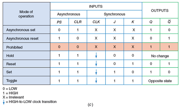
At the same time, NAND 2 is disabled, because it only has one of its inputs (K) at logic 1, its feedback input is at logic 0 because of the feedback from Q. OperationĪs a starting point, assume that both J and K are at logic 1 and the outputs Q = 0 and Q = 1, this will cause NAND 1 to be enabled, as it has logic 1 on two (J and Q) of its three inputs, requiring only a logic 1 on its clock input to change its output state to logic 0. The purpose of this feedback is to eliminate the indeterminate state that occurred on the SR flip-flop when both inputs were made logic 0 at the same time. On NAND 2 the reset input (R) of Fig 5.2.7 has been replaced by input K and there is an additional feedback connection from Q.

5.4.1 is now a three input gate and the set input (S) been replaced by an input labeled J, and the third input provides feedback from the Q output. 5.4.1, it can be seen that although the clock input is the same as in the clocked SR flip-flop, gate NAND 1 in Fig. 5.2.7, (Digital Electronics Module 5.2) but in Fig.

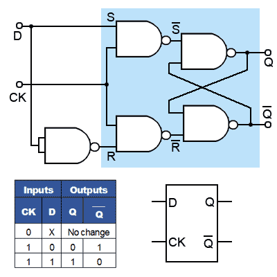
The circuit is similar to the clocked SR flip-flop shown in Fig. 5.4.1 shows the basic configuration (without S and R inputs) for a JK flip-flop using only four NAND gates. The JK Flip-flop is also called a programmable flip-flop because, using its inputs, J, K, S and R, it can be made to mimic the action of any of the other flip-flop types.įig.


 0 kommentar(er)
